
Wind Tunnel Testing of the RoofRider on an Intermodal Train at BYU
- Spencer Maynes
- Feb 21, 2022
- 5 min read

Written by Nathan Richey, Caleb Reidhead, Ammon Markstaller, Dallin Taylor, Brad Corbett, Alec Linderman, Taylor Farnsworth, Wayne Kennedy and Joseph F. Prince SUMMARY: This paper reports 1/29th scale wind tunnel testing of drag reducing deflectors on an intermodal train model. The deflectors had a constant triangular cross-section and were applied symmetrically to the front and back of the top edges of the intermodal containers. The tests were performed in a wind tunnel with a test section having dimensions of 914 mm x 457 mm x 457 mm at five different speeds ranging from 7.6 to 36 m/s (27 to 130 kph). The train consisted of a streamlined nose cone followed by two and a half double stacked containers. The drag across the second container was measured with a three-axis sting force/moment balance. From a design of experiments with eight runs, the deflector height was identified as the most critical dimension. The optimal triangular shape achieved an average drag reduction of 7.8% compared to the control runs without deflectors. Keywords: drag reduction, intermodal trains, aerodynamics 1. INTRODUCTION Intermodal trains present a unique opportunity to use drag reducing devices that rely on the interactions among the cars. One such technique achieves a drag reduction by using deflectors that reduce the high velocity impingement and consequently decrease the high pressure on the front of the downstream car (Maynes et al., 2019). This approach is different from reducing the separated flow region downstream of a bluff body. Vortex generators, some rear spoilers, and suction on the downstream side of a bluff body all decrease drag by minimizing the flow separation (Bulathsinghala et al., 2017; Krajnovic, 2008; Roumeas et al., 2009).
Designing deflectors for intermodal train cars also introduces some specific geometric constraints. The intermodal shipping containers are designed to be stacked, so the deflector geometries cannot interfere with the stacking of the containers. This limits the application of the deflectors to the top edges of the container. The orientation of the containers is also not known a priori. Thus, the deflectors must be applied symmetrically to the leading and trailing edges of the containers.
This paper presents wind tunnel testing of drag reducing triangular deflectors. The specific shape of the deflectors was optimized through a design of experiments demonstrating the potential drag reduction that can be achieved on intermodal train cars.
2. METHODOLOGY 2.1. Wind Tunnel Wind tunnel testing was performed to optimize deflector shape to maximize the drag reduction. A 1/29th G scale intermodal train model consisting of two and a half double stacked containers was used for the testing as depicted in Fig. 1.
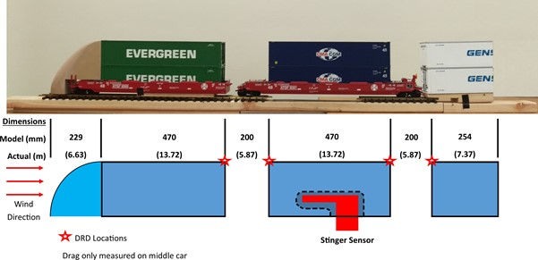
Figure 1. Train model dimensions and layout showing drag reducing deflector (DRD) locations To minimize the effect of a short train, a streamlined nose cone was attached to the first well car. Because of the limited test section of the wind tunnel, the third container was cut as shown in Fig. 1. Watkins et al. showed this shortened train length is adequate to remove much of the end effects of the train (Watkins et al., 1992). The first and last containers were fixed in place while the drag across the second container was measured with a three-axis sting force/moment balance. The sting was tested with a sphere in the wind tunnel to verify the calibration. The triangular deflectors with a constant cross-section were applied symmetrically to front and back of the top edges of the intermodal containers. The tests were performed in a wind tunnel with a test section of 914 mm x 457 mm x 457 mm with a flow contraction of 6.25 to 1. The tests were conducted at five different speeds ranging from 7.6 to 36 m/s (27 to 130 kph). A control run was performed before each run with deflectors, and all runs were replicated three times and averaged.
2.2. Shape Optimization A concept design process was followed to select an initial deflector design (Mattson and Sorensen, 2020). While other deflector geometries were considered, a constant, triangular cross-section deflector was selected based on preliminary testing. The exact shape and size of the triangular deflector was optimized to maximize drag reduction utilizing a 2^3 factorial experiment. The three factors considered were the inside length (the section of the triangle closest to the middle of the container), the outside length, and the deflector height as shown in Fig. 2.
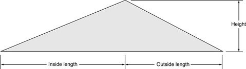
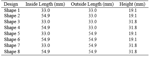
Figure 2. Schematic of deflector geometry The shapes and their geometries are specified in Table 1. Each factor has a high and low value that were determined based on preliminary wind tunnel testing as well as physical constraints of the intermodal containers for shipping. Specifically, the height was limited to allow for stacking without interference between the containers. Table 1. Table of deflector geometries for each shape
3. RESULTS Fig. 3 shows the results for each triangular shape at the five wind speeds averaged over the three replicates. In general, the drag reduction is lowest at 7.6 m/s, rises to a maximum at 15.8 m/s, and decreases marginally with increasing speed up to 36.2 m/s. It is clear shapes 3 and 4 achieve the largest drag reduction compared to the other shapes for each wind speed. If the data is averaged over all wind speeds, shape 4 achieves the highest drag reduction of 7.8%. Shapes 7 and 8 follow next in performance except when considering the 7.6 m/s speed which has some scatter in the results.
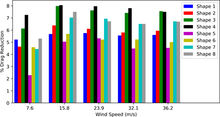
Figure 3. Drag reduction plotted at different wind speeds for each shape 4. DISCUSSION The deflectors that produced the largest drag reduction were shapes 3, 4, 7, and 8. These were the shapes with the larger height of 31.8 mm. In the statistical analysis, the only statistically significant factor was the height, so it seems reasonable that all of the best performers would have the same value for this parameter.
While not statistically significant, the next most important factor was the outside length where the better performing value was 33.0 mm. This factor explains the increased drag reduction of 3 and 4 as compared to 7 and 8 and the enhanced performance of 1 and 2 as compared to 5 and 6. It is conjectured that the drag reduction is achieved because some of the high velocity air is deflected away from the top of the downstream car front face. Because of mass conservation, this air is replaced by lower velocity air that has been decelerated due to the train’s interaction with the ground. This reduces the pressure drag and may enable less disruptive flow reattachment to the downstream container. 5. CONCLUSIONS This paper presents wind tunnel testing of drag reducing triangular deflectors. The specific shape of the deflectors has been optimized through a design of experiments with eight cases. The deflector height was identified as the most critical dimension. The optimal triangular shape achieved an average drag reduction of 7.8% compared to the control case without deflectors.
ACKNOWLEDGEMENTS We would like to acknowledge the support of a US Class 1 railroad and of the BYU Capstone Program (Todd et al., 1993). We also acknowledge Deflect LLC.
REFERENCES
Bulathsinghala, D. S., Wang, Z., and Gursul, I., 2017. “Mini-Spoilers for Afterbody Base Drag Reduction”. Proceed- ings of 47th AIAA Fluid Dynamics Conference.
Krajnovic, S., Sept. 2008. “Optimization of Aerodynamic Properties of High-Speed Trains with CFD and Response Surface Models”. Proceedings of vol. 41, pp. 197–211.
Mattson, C. and Sorensen, C., 2020. Product Development: Principles and Tools for Creating Desirable and Transfer- able Designs. Springer Nature Switzerland.
Maynes, S., Kennedy, W., Hansen,R., and Golsch,K., 2019. “Deflector for Vehicle”.US Patent Application 16/721,009.
Roumeas, M., Gillieron, P., and Kourta, A., Aug. 2009. Drag reduction by flow separation control on a car after body. International Journal for Numerical Methods in Fluids 60, 1222–1240.
Todd, R. H., Sorensen, C. D., and Magleby, S. P., 1993. Designing a Senior Capstone Course to Satisfy Industrial Customers. Journal of Engineering Education 82, 92–100.
Watkins, S., Saunders, J., and Kumar, H., June 1992. Aerodynamic drag reduction of good trains. Journal of Wind Engineering and Industrial Aerodynamics 40 (2), 147–178.


Comments